
 HOTLINE:+8613974960765 +8618507312158 HOTLINE:+8613974960765 +8618507312158


— Knowledge —
— PRODUCTS —
 Service Hotline +8613974960765
Email:susie@hnljpump.com
Mobile:+8618507312158
TEL:+8613974960765
vertical turbine pump
Publication date:2025/1/31 16:22:52 popularity: [content:visits]
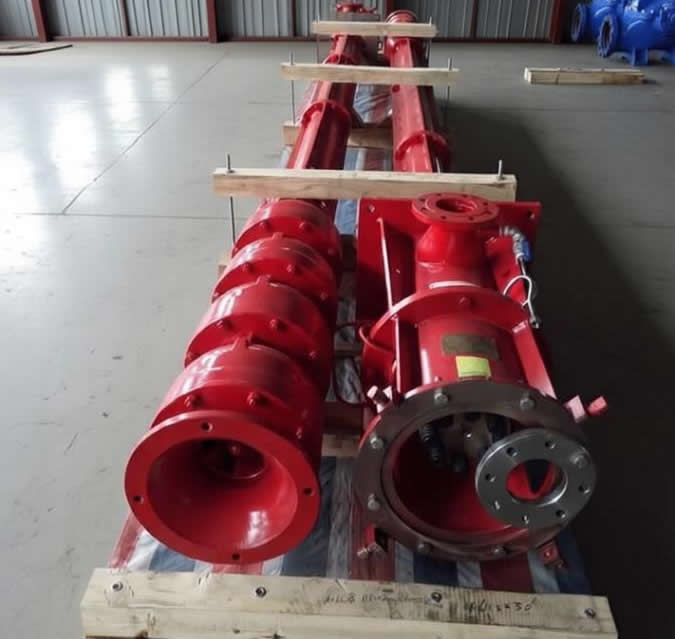
The core of the installation and use specifications for vertical submerged multistage long-shaft deep-well fire turbine pumps revolves around four major aspects: "well condition adaptation, standardized installation, scientific start-stop, and regular operation and maintenance". Strict implementation throughout the entire process can completely avoid common faults such as shaft breakage, motor burnout, and pump body stagnation, ensuring long-term stable operation of vertical multistage submerged long-shaft deep-well fire turbine pump equipment.
· Well condition adaptation verification: The diameter of the pump body should be at least 50mm smaller than the well diameter. The actual well depth should correspond to a dynamic water level height above the ground that is less than 80%-90% of the pump's rated head, with a 10%-20% head margin reserved. The sand content in the conveying medium must be ≤0.01%, and the particle size of impurities must be ≤0.1mm.
· Equipment and tool inspection: Unpack and count all parts. Manually rotate the pump shaft to ensure it is flexible and free of stagnation. Use a micrometer to measure the total runout of the drive shaft, which should be ≤0.4mm, otherwise it must be straightened. Prepare special tools such as a tripod, winch, chain pliers, pipe wrench, multimeter, etc.
· Well condition pre-treatment: For new wells or wells that have been out of use for a long time, first use a submersible pump to pump and drain for 1-2 hours to thoroughly remove sediment and debris at the bottom of the well. Confirm that the pump body is placed 1-3m below the dynamic water level and at least 5m away from the well bottom to prevent wear caused by inhaling sediment.
00001. Component Pre-treatment: Clean the threads and mating surfaces of all lifting pipes and drive shafts with kerosene, and apply a uniform layer of butter; rubber bearings must not come into contact with oil, and should be evenly coated with stone powder to prevent rubber deformation and failure.
00002. Step-by-step lifting and lowering: First, lift the working components and the bottom valve into the well and secure them to the wellhead sleeper with clamps. Then, connect the lifting pipe, transmission shaft, and bearing body in sequence. Check the coaxiality of the transmission shaft every 10m of lowering, and immediately investigate the cause if there is excessive deviation.
00003. Installation of well components: When connecting the pump base to the lifting pipe, if the well casing is tilted, it is necessary to fill the gap on the bottom surface of the pump base with iron blocks. It is forbidden to forcibly align the pump base with a horizontal reference, otherwise it is extremely easy to cause shaft breakage during operation.
00004. Motor alignment adjustment: After connecting the motor drive shaft to the long shaft with a coupling, adjust the axial clearance: for a thread with a pitch of 2mm, rotate the adjusting nut one turn to raise the drive shaft by 2mm, ensuring that the rotor's vertical movement meets the factory requirements.
00005. Electrical Safety Specifications: The motor should be connected to a dedicated control box equipped with overload and leakage protection. Use a multimeter to check that the motor insulation resistance is ≥0.5MΩ and the system grounding resistance is ≤4Ω. Cable connectors should be wrapped and sealed with multiple layers of waterproof tape to prevent water ingress and short circuits.
⚡ Startup and Operation Specifications · Verification before Initial Startup: Close the outlet valve and briefly power on for 10-20 seconds to confirm that the motor rotation direction is consistent with the arrow marked on the pump body. If it rotates in the opposite direction, swap any two live wires of the three-phase motor. Reverse operation is prohibited.
· On-load startup operation: After adjusting the opening of the outlet valve to 50%, initiate the official startup. Gradually open the valve fully, ensuring that the operating current does not exceed the rated current of the motor, and maintain the outlet pressure within the design value range.
Operational inspection requirements: During daily operation, record the current, pressure, and bearing temperature every 2 hours. The temperature rise of the bearing must not exceed 35°C above the ambient temperature. The operational vibration value should be ≤1.8mm/s. In the event of abnormal noise or severe vibration, the machine must be stopped immediately for troubleshooting.
· No idle running: It is strictly prohibited to idle the pump body above the dynamic water level throughout the entire process. Otherwise, it will quickly burn out the rubber/silicon carbide guide bearing, causing severe wear and fracture of the shaft system.
Normal shutdown procedure: First, gradually close the outlet valve, then cut off the motor power supply. It is prohibited to directly power off and shut down with load, to avoid damage to the pump body and pipeline due to water hammer impact.
Regular maintenance requirements: Check the wear condition of the chrome-plated section of the drive shaft every quarter. If the wear exceeds the standard, replace the drive shaft in the up-down direction and continue to use it to extend its lifespan. Complete a full-equipment linkage test before the flood season. For pumps that have been out of use for a long time, manually rotate them 2-3 turns every month to prevent rust and seizure of the shaft system.
· Fault Handling Guidelines: In the event of no water output or insufficient flow, priority should be given to checking whether the impeller is blocked and whether there is any leakage at the connecting thread of the lifting pipe. Forced operation for extended periods with faults is prohibited to avoid motor overload and burnout.
Related Recommendations

Service hotline
screenshots ,WeChat Scan the Qr Code
WeChat:ljpump6666